D5212Q G.M. International s.r.l.
GM International

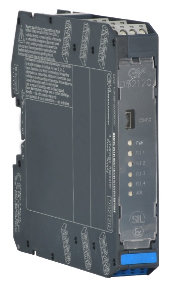
D5212Q
I.S. SIL2 2/4-Wire Transmitter Power Supply

The Repeater Power Supply D5212 module is a high integrity analog input interface suitable for applications requiring SIL 2 level in safety related systems for high risk industries. It provides a fully floating dc supply for energizing conventional 2 wires 0/4-20 mA, active or passive, transmitters located in Hazardous Area, and repeats the current in floating circuit to drive Safe Area loads. The module is fully configurable to achieve input/output multiplexing, scaling, duplication, inversion, and input elaboration (addition, subtraction, low/high selection). An additional alarm contact can be (de-)activated on programmable input trip points, including hysteresis and delays. Configuration and diagnostic parameters are programmable and can also be monitored/set through Modbus.

FEATURES

  • SIL 2 / SC 3
  • Input from Zone 0/Div. 1
  • Installation in Zone 2/Div. 2
  • 0/4-20 mA Active-Passive Input, Source Output
  • Duplication/inversion/scaling output
  • Input operations (sum, dif, max, min) available
  • Input and Output short circuit proof
  • Out of range fault detection
  • Alarm output with user-settable trip points
  • Modbus RTU RS-485 for monitor & configuration
  • Fully programmable operating parameters
  • High Accuracy, µP controlled A/D converter
  • Three port isolation, Input / Output / Supply
  • High Density, four channels per unit
STATUS

 
   ACTIVE
Product lifecycle policy (EN)

Request a free and personalized quotation!

Technical Data


Supply

Type 24 Vdc nom (21.5 to 30 Vdc), reverse polarity protected.
Current Consumption 200 mA @ 24 Vdc with 20 mA in/out, typical.
Power Dissipation 2.75 W @ 24 Vdc with 20 mA in/out, typical.

Input

Type 0/4 to 20 mA (2 wire Tx current limited ≈ 25 mA) or separately powered inputs (only for channels 1 and 2).
Transmitter line voltage 14.5 V typical, 14.0 V minimum, @ 20 mA.
Integration time 500 ms.

Output

Type 0/4 to 20 mA, on max. 300 Ω load source mode, current limited ≈ 25 mA.
Response time 100 ms (10 to 90 % step change).

Alarm

Trip point range within rated limits of the input sensor.
ON-OFF delay time 0 to 1000 s, 100 ms step.
Hysteresis within rated limits of input sensor.
Output voltage free SPST photoMOS: 100 mA, 60 Vdc (≤ 1 V voltage drop).

Modbus interface

Type Modbus RTU RS-485 up to 57.6 kbps for monitor/configuration/control.

Input performance

Ref. Conditions 24 V supply, 250 Ω loads, 23 ± 1 °C ambient temperature.
Calibration accuracy ≤ ± 0.05 % FSR
Linearity accuracy ≤ ± 0.05 % FSR
Temp. influence ≤ ± 0.01% of input FSR for a 1 °C change

Analog output performance

Ref. Conditions 24 V supply, 250 Ω loads, 23 ± 1 °C ambient temperature.
Calibration accuracy ≤ ± 0.05 % FSR
Linearity accuracy ≤ ± 0.05 % FSR
Temp. influence ≤ ± 0.005 % of output FSR for a 1 °C change

Isolation

Test Voltage I.S. In/Out 1.5 kV; I.S. In/Supply 1.5 kV; Out/Supply 500 V; I.S. In/Alarm 1.5 kV; Supply/Alarm 500 V; Out/Alarm 500 V.

Safety description

Equipment Associated apparatus and non-sparking electrical equipment.
Safety parameters Uo = 24.1 V, Io = 86 mA, Po = 516 mW at terminals 13-14, 15-16, 17-18, 19-20. Uo = 1.1 V, Io = 56 mA, Po = 16 mW at terminals 21-22, 23-24. Ui = 30 V at terminals 21-22, 23-24. Ii = 128 mA at terminals 21-22, 23-24. Ci = 2.1 nF, Li = 0 nH at terminals 21-22, 23-24. Um = 250 Vrms or Vdc, -40 °C ≤ Ta ≤ 70 °C.

Mounting

Type DIN-Rail 35 mm, with or without Power Bus or on custom Term. Board.
Weight about 120 g.
Connection by polarized plug-in disconnect screw terminal blocks to accomodate terminations up to 2.5 mm² (13 AWG).
Dimensions Width 22.5 mm, Depth 123 mm, Height 120 mm.

Data Sheet


Datasheet of D5212 ( EN | FR | DE | ES | IT | CN | JA | PT )

Instruction Manual


Instruction Manual D5212 ( EN )
EAC safety instruction manual for D5000 series ( EN | RU )
EAC Passport of D5212 ( RU )
Instruction Manual D5000-D5200 Series ( EN )
Instruction Manual SWC5090 ( EN | RU )
Safety manual D5212 ( EN )
ATEX safety instruction manual for D5000 series ( EN | IT )
CCC Ex safety instruction manual for D5000 series ( EN | CN )
Ex safety instruction manual for D5000 series ( RU )
UL Control Drawing D5212 ( EN )

Certifications


Type Description Area Number Issued by Issue Date
ATEX UL ATEX D5212 Series English Certificate ( EN ) Europe DEMKO 18 ATEX 2017X UL 2021-11-12
Ex D5000 CCC certificate for China ( EN ) China 2020322316000978 NEPSI 2024-03-22
Ex EAC Ex Certificate for D5000 Series ( RU ) Eurasian Community ЕАЭС RU С-IT.AA87.В.01310/24 CCVE 2024-06-13
Ex UL-cUL D5212 Divisions and Zones ( EN ) North America 20181029-E222308 UL 2018-10-29
FSM TUV IT 22 SIL 0093 Functional Safety Certificate ( EN ) International TUV IT 22 SIL 0093 TUV_SUD 2022-07-25
IECEx UL IECEx D5212 Series English Certificate ( EN ) International IECEx ULD 18.0013X UL 2021-11-12
Maritime KR Maritime Certificate D5000 Series ( EN ) International MIL20769-EL002 KR 2024-06-26
Maritime DNV Maritime Certificate TAA00001U0 for D5000 series for website ( EN ) International TAA00001U0 DNV-GL 2024-04-02
Metrological Metrological Certificate Belarus for D5000/D6000 Series ( BE ) Belarus 15507 ROSSTANDART 2022-08-30
Metrological Metrological Certificate Kazakhstan for D5000/D6000 series ( KK ) Kazakhstan 1152 KMC 2021-08-05
Metrological Metrological Certificate Russia for D5000/D6000 series ( RU ) Russia OC.C.32.004.A n. 77881 ROSSTANDART 2020-07-28
SIL TUV C-IS-722160171 SIL Certificate Summary ( EN ) International C-IS-722160171 TUV_SUD 2022-10-14

Declarations of Conformity


EU Declaration of Conformity for D5212 ( EN | IT )
EU Declaration of Conformity for RoHS, ASBESTOS. ( EN )
Declaration of Conformity G3 compliance ( EN )

Dimensions


Image of D5212_size

Connections


Drawings


2d_drawing_D5200_dwg ( EN )
3d_drawing_D5200_dwg ( EN )
3d_drawing_D5200_stp ( EN )

Software


SWC5090 - Configurator for D5000/D5200, D6000/D6200 Series isolators ( EN )
Instruction Manual SWC5090 ( EN )