Supply |
|
Type
|
24 Vdc nom (21.5 to 30 Vdc), reverse polarity protected.
|
|
Current Consumption
|
110 mA @ 24 Vdc with 20 mA input/output and alarm relays energized, typical.
|
|
Power Dissipation
|
2.3 W @ 24 Vdc with 20 mA input/output and alarm relays energized, typical.
|
Input |
|
Type
|
0/4 to 20 mA (separately powered input, voltage drop ≤ 0.5 V) or 4 to 20 mA (2 wires Tx current limited ≈ 25 mA), or voltage input ±12 V.
|
|
Integration time
|
100 ms.
|
|
Input range
|
0 / +25 mA for current, ± 12 V for voltage.
|
|
Transmitter line voltage
|
15.5 V typical, 15.0 V minimum, @ 20 mA.
|
Acknowledgement input |
|
Type
|
Logic level reverse polarity protected.
|
|
Voltage range
|
0 V ≤ OFF ≤ 5 V, 18 V ≤ ON ≤ 30 V.
|
|
Current Consumption
|
10 mA @ 24 Vdc, typical.
|
Output |
|
Type
|
Fully customizable 0/4 to 20 mA, on max. 300 Ω load source mode, current limited @ 25 mA.
|
|
Transfer characteristic
|
linear, direct or reverse, square root.
|
|
Response time
|
≤ 100 ms (10 to 90% step change).
|
Alarm |
|
Trip point range
|
within rated limits of input sensor.
|
|
Output
|
two voltage free SPDT relay contacts.
|
|
Contact rating
|
4 A 250 Vac 1000 VA, 4 A 250 Vdc 120 W (resistive load).
|
|
DC and AC load breaking capacity
|
refer to Instruction Manual.
|
Modbus interface |
|
Type
|
Modbus RTU RS-485 up to 115.2 kbps for monitor/configuration/control.
|
Isolation |
|
Test Voltage
|
I.S. In/Other 1.5 kV; Alarms/Other 1.5 kV; Alarm/Alarm 1.5 kV; Out/Supply 500 V; Out/Ack 500 V; Ack/Supply 500 V.
|
Environmental conditions |
|
Operating temperature
|
temperature limits –40 to +70 °C.
|
|
Storage temperature
|
temperature limits -45 to +80 °C.
|
Safety description |
|
Equipment
|
Associated apparatus and non-sparking electrical equipment.
|
|
Safety parameters
|
Uo = 26 V, Io = 91 mA, Po = 588 mW at terminals 13-14
Uo = 1.1 V, Io = 56 mA, Po = 16 mW at terminals 14-16
Uo = 1.1 V, Io = 0.012 mA, Po = 0.004 mW at terminals 15-16
Ui = 30 V at terminals 14-16 or 15-16, Ii = 128 mA at terminals 14-16, Ci = 2.1 nF, Li = 0 nH at terminals 13-14-15-16.
Um = 250 Vrms or Vdc, -40 °C ≤ Ta ≤ 70 °C.
|
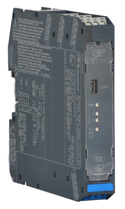
Mounting |
|
Type
|
DIN-Rail 35 mm, with or without Power Bus or on custom Term. Board.
|
|
Weight
|
about 120 g.
|
|
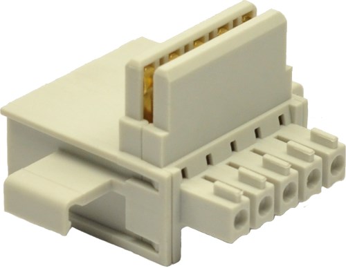
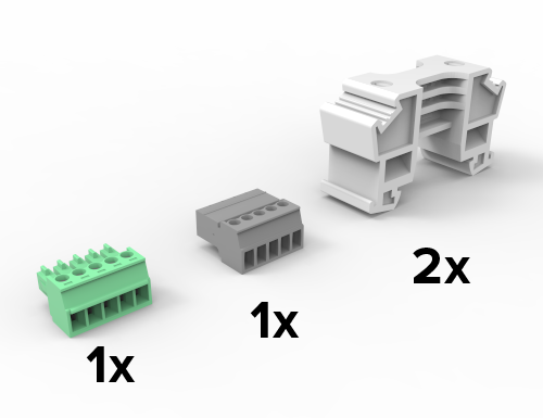
Connection
|
by polarized plug-in disconnect screw terminal blocks to accommodate terminations up to 2.5 mm² (13 AWG).
|
|
Dimensions
|
Width 22.5 mm, Depth 123 mm, Height 120 mm.
|