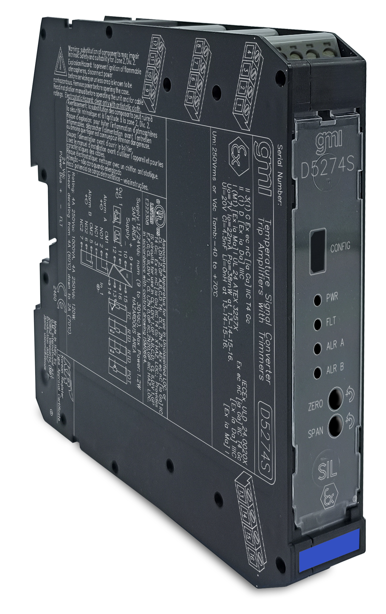
D5274S G.M. International s.r.l.
GM International

D5274S
I.S. SIL2 Temp. Trip Amplifier with Zero/Span Trimmers

The Temperature Converter & Trip Amplifier D5274 accepts a low level dc signal from millivolt/thermocouple or 2-3-4 wire resistance/RTD or potentiometer sensors, located in Hazardous Area, and converts, with isolation, the signal to drive a Safe Area load, suitable for applications requiring SIL 2 level in safety related systems for high risk industries. Output signal can be direct or reverse. Front trimmers allow easy zero & span current adjustment. Cold junction compensation can be programmed as automatic, using an internal or external temperature sensor or fixed to a user customizable temperature value. D5274S offers two independent trip amplifiers via two SPDT output relays, whose thresholds are fully programmable. Extended power supply range guarantees functionality at 24 Vdc as well as 12 Vdc nominal voltage.

FEATURES

  • SIL 2 / SC 3 (pending)
  • Input from Zone 0/Div. 1
  • Installation in Zone 2/Div. 2
  • mV, TC, 2/3/4wire res./RTD or potentiometer input
  • Two independent Trip Amplifiers (SPDT relay contacts)
  • Inversion/scaling/custom output
  • Selectable CJC: internal PT1000, external RTD or fixed
  • Burnout fault monitor
  • Alarm output with user-settable trip points
  • Zero/span output current trimmers
  • Extended power supply for 12/24 Vdc nominal voltage
  • Fully programmable operating parameters
  • High Accuracy, µP controlled A/D converter
  • Three port isolation, Input/Output/Supply

STATUS

 
   ACTIVE
Product lifecycle policy (EN)

CHANNELS

1

Request a free and personalized quotation!

Technical Data


Supply

Voltage 12/24 Vdc nom (9 to 30 Vdc), reverse polarity protected.
Current Consumption 45 mA @ 24 Vdc with 20 mA output and relays energized, typical.
Power Dissipation 1.0 W @ 24 Vdc with 20 mA output on 250Ω load and relays energized, typical.

Input

Type Millivolt/thermocouple, 2-3-4 wire resistance/RTD or 3 wire potentiometer. Refer to Instruction Manual for more details.
Response time 1 s.
Input range ±500 mV (mV), 0-5 kΩ (res), up to 10 kΩ (pot).

Output

Type Current 0/4 to 20 mA.
Maximum load resistance 300 Ω.
Maximum output voltage 30 V.
Minimum output voltage 15 V.
Short circuit current 24 mA, typical
Transfer characteristic linear, direct or reverse on all input sensors.
Trimmers two front trimmers allow easy independent zero/span calibration. Trimmers can be modified in range or they can be excluded.

Alarm

Trip point range within rated limits of input sensor.
Output two voltage free SPDT relay contacts.
Contact rating 4 A 250 Vac 1000 VA, 4 A 250 Vdc 120 W (resistive load). Linear derating from 4 A (60 °C) down to 2 A (70 °C).

Fault

Type Fault can be issued in case of input sensor burnout.
Response time 1 s.
Fault signalling common fault bus, alarm contacts, output current.

Input performance

Ref. Conditions 24 Vdc supply, 250 Ω load, 23 ± 1 °C Tamb.
Input accuracy Refer to Instr. Manual for temperature sensor accuracy.
Linearity accuracy ≤ ±25 μV (mV), ±0.25 Ω (res), ±0.05% (pot).
Calibration accuracy ≤ ±30 μV (mV), ±0.5 Ω (res).
Temp. influence ≤ ±10 μV (mV), ±0.2 Ω (res), ±0.02% (pot).

Output performance

Ref. Conditions 24 Vdc supply, 250 Ω load, 23 ± 1 °C Tamb.
Linearity accuracy ≤ ±10 μA.
Calibration accuracy ≤ ±10 μA.
Temp. influence ≤ ±1 μA.

Isolation

Test Voltage I.S. In/Out 2.5 kV; I.S. In/Supply 2.5 kV; I.S. In/Alarms 2.5 kV; Out/Supply 500V; Out/Alarms 1.5 kV; Alarms/Supply 1.5 kV; Alarms/Alarms 1.5 kV.

Environmental conditions

Operating temperature temperature limits –40 to +70 °C.
Storage temperature temperature limits –45 to +80 °C.

Safety description

Equipment Associated apparatus and non-sparking electrical equipment.
Safety parameters Uo = 7 V, Io = 22 mA, Po = 38 mW at terminals 13-14-15-16. Um = 250 Vrms or Vdc, -40 °C ≤ Ta ≤ 70 °C.

Mounting

Type DIN-Rail 35 mm, with or without Power Bus.
Weight about 195 g.
Connection by polarized plug-in disconnect screw terminal blocks to accomodate terminations up to 2.5 mm² (13 AWG).
Dimensions Width 22.5 mm, Depth 123 mm, Height 120 mm.

Data Sheet


Datasheet of D5274S ( EN )

Instruction Manual


Instruction Manual D5274 ( EN )
ATEX safety instruction manual for D5000 series ( EN | IT )
UL Control Drawing D5274 ( EN )

Certifications


Type Description Area Number Issued by Issue Date
ATEX UL ATEX D5274 Series English Certificate ( EN ) Europe UL 24 ATEX 3257X UL 2024-09-20
Ex UL-cUL D5274 Divisions and Zones ( EN ) North America UL-US-2434214-0 UL 2024-10-30
IECEx UL IECEx D5274 Series English Certificate ( EN ) International IECEx ULD 24.0020X UL 2024-09-20
Maritime KR Maritime Certificate D5000 Series ( EN ) International MIL20769-EL002 KR 2024-06-26

Declarations of Conformity


EU Declaration of Conformity of D5274 ( EN | IT )

Dimensions


Image of D5274S_size

Connections


Software


SWC5090 - Configurator for D5000/D5200, D6000/D6200 Series isolators ( EN )
Instruction Manual SWC5090 ( EN )