X1-IS-UNI-01-S G.M. International S.p.A.
GM International

X1-IS-UNI-01-S
I.S. SIL3/2 Universal Module

The Universal X1-IS-UNI-01 module is a high integrity interface suitable for applications requiring SIL 3 or SIL 2 level (depending on applications) in safety related systems for high risk industries. Thanks to its high flexibility, it can interface 2-wire active/passive 4-20 mA (AI), smart positioners (AO), switches and proximity detectors (DI), as well as solenoid valves and other process control devices (DO) located in Hazardous Area. HART® communication is supported for both active and passive transmitters, and I/P. The module always sinks current and the Termination Board extends its use to source loops. Programmable line and load open/short circuit detection and out-of-range current fault is also provided. The module automatically matches the application, without reprogramming; if required, it can be re-calibrated through the configuration software. To ease maintenance operations, field devices can be disconnected through a two-position insertion/extraction mechanism. This product requires a dedicated Termination Board.

FEATURES

  • SIL 3/2 depending on applications / SC 3
  • Input from Zone 0 / Division 1
  • Installation in Zone 2 / Division 2
  • Loop disconnection to ease maintenance operations
  • Suitable for AI, AO, DI and DO applications without configuration
  • HART® compatible (passive and active AI/AO loops)
  • Line & Load short/open circuit programmable diagnostics
  • Out-of-range fault with programmable thresholds
  • Digital calibration available through configuration software
  • Input and Output short circuit proof
  • Field fault mirroring to the DCS/PLC UNI Card
  • High Accuracy
  • Three port isolation, Input/Output/Supply

STATUS

 
   ACTIVE
Product lifecycle policy (EN)

CHANNELS

1

Request a free and personalized quotation!

Technical Data


General

AI Power dissipation 0.90 W (pass. Tx), 1.05 W (act. Tx) with 20 mA, 24 V + 250 Ω @ 24 Vdc, typical.
AO Power dissipation 0.75 W with 20 mA on I/P out @ 24 Vdc, typical.
DI Power dissipation 0.95 W with short circuit input @ 24 Vdc, typical.
DO Power dissipation 1.60 W with 40 mA, 1.40 with 35 mA @ 24 Vdc, typical.

System Supply

Voltage 24 Vdc nom (18 to 30 Vdc).
AI Current consumption 32 mA (passive Tx), 18 mA (active Tx) with 20 mA @ 24 Vdc, typical.
AO Current consumption 30 mA with 20 mA on I/P out @ 24 Vdc, typical.
DI Current consumption 30 mA with short circuit input @ 24 Vdc, typical.
DO Current consumption 67 mA with 40 mA @ 24 Vdc, typical.

System In/Out

Type Current 0 to 40 mA, mirrored from Field. The module always sinks current and the Termination Board extends its use to source loops.
Response time 5 ms.
Maximum load 600 Ω (AI usage).
Minimum voltage 15 V (AI, DI, DO usage).
Maximum voltage 30 V (all applications).

Field In/Out

Type Field interface specs depend on terminals and usage.
Current limitation 45 mA, typical, for all applications.
AI Current 4 to 20 mA, passive or active Tx + HART.
AI Passive Tx line voltage 15.5 V minimum @ 20 mA.
AI Active Tx voltage drop 6.5 V maximum @ 20 mA.
AO Current 4 to 20 mA + HART.
AO Maximum load 600 Ω.
DI 8 V/1 kΩ typical, according to NAMUR standard.
DO 0 to 40 mA, linear derating from 40 mA (60 °C) to 35 mA at (70 °C).
DO Output voltage 8.5 V minimum @ 40 mA.

Fault

Type Load short/open with settable limits on voltage, current and resistance.
Fault signalling common fault & fault mirroring on DCS/PLC IO.

Performance

Ref. Conditions 24 V supply, 250 Ω load, 23 ± 1 °C Tamb.
Calibration accuracy ≤ ± 20 µA.
Linearity accuracy ≤ ± 20 µA (4 to 20 mA), ± 60 µA (0 to 40 mA).
Temp. influence ≤ ± 2 µA/°C.

Isolation

Type Field InOut/System InOut 2.5 kV; Field InOut/System Supply 2.5 kV; System InOut/System Supply 500 V.

Environmental conditions

Operating temperature temperature limits –40 to +70 °C
Storage temperature temperature limits –45 to +80 °C.

Safety description

Equipment Associated apparatus and non-sparking electrical equipment.
Safety parameters Uo = 26.7 V, Io = 92 mA, Po = 610 mW at terminals A-Z. Uo = 10.7 V, Io = 11 mA, Po = 29 mW at terminals C-Z. Uo = Uo = 1.1 V, Io = 56 mA, Po = 16 mW at terminals B-Z. Ui = 30 V, Ii = 120 mA, Ci = 0.6 nF, Li = 0 µH at terminals B-Z. Um = 250 Vrms or Vdc, -40 °C ≤ Ta ≤ 70 °C.

Mounting

Type On custom Termination Board.
Weight about 50 g.
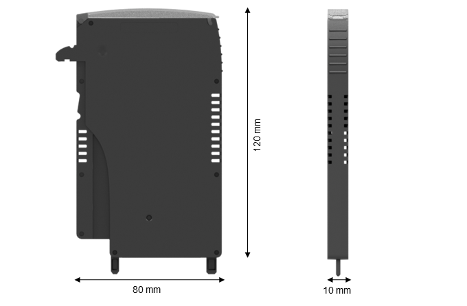
Dimensions Width 10 mm, Depth 80 mm, Height 120 mm.

Data Sheet


Datasheet of X1-IS-UNI-01 ( EN )

Instruction Manual


CCC Ex safety instruction manual for X1 series ( EN | CN )
Instruction Manual X1 Series ( EN )
Instruction Manual of X1-IS-UNI-01 ( EN )
Safety Information of X1-IS-UNI-01-S ( EN )
FM Control Drawing of X1-IS-UNI-01 ( EN )
Safety Manual of X1-IS-UNI-01-S ( EN )

Certifications


Type Description Area Number Issued by Issue Date
ATEX FM ATEX I.S. X1 Series English Certificate ( EN ) Europe FM23ATEX0038X FM 2025-08-13
Ex X1 CCC certificate for China ( EN ) China 2025322310006991 NEPSI 2025-11-12
Ex FM US X1 Series Divisions and Zones English Certificate ( EN ) North America FM23US0073X FM 2025-08-12
Ex FM Canada X1 Series Divisions and Zones English Certificate ( EN ) North America FM23CA0055X FM 2025-08-12
IECEx FM IECEx X1 Series English Certificate ( EN ) International IECEx FMG 23.0018X FM 2025-08-12
SIL TUV IT 25 SIL 0587 A SIL Certificate Summary ( EN ) International TUV IT 25 SIL 0587 A Rev.1 TUV_SUD 2025-09-19
UKEx FM UKEx I.S. X1 Series English Certificate ( EN ) United Kingdom FM23UKEX0039X FM 2025-08-14

Declarations of Conformity


EU Declaration of Conformity of X1-IS-UNI-01 ( EN | IT )
UK Declaration of Conformity of X1-IS-UNI-01 ( EN )

Dimensions


Image of X_size

Connections


Drawings


3D_drawing_X1-Cartridge_stp ( EN )