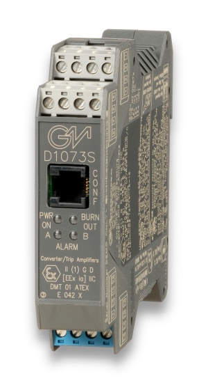
Supply |
|
Voltage
|
24 Vdc nom (20 to 30 Vdc) reverse polarity protected,
ripple within voltage limits ≤ 5 Vpp.
|
|
Current Consumption
|
65 mA with 20 mA output and relays energized typical.
|
|
Power Dissipation
|
1.5 W with 24 V supply, 20 mA output and relays energized typical.
|
|
Max. power consumption
|
at 30 V supply voltage, overload condition,
relays energized and PPC1090 connected, 2.1 W.
|
Input |
|
Type
|
millivolt or thermocouple type A1, A2, A3, B, E, J, K, L, Lr, N, R, S, S1, T, U or
3-4 wires RTD Pt100, Pt200, Pt300 to DIN43760, Pt100 (0.3916), Ni100, Ni120 or
Pt500, Pt100, Pt50, Cu100, Cu53, Cu50, Cu46 (russian standard) or
3 wires transmitting potentiometer (50 Ω to 20 KΩ).
|
|
Integration time
|
500 ms.
|
|
Resolution
|
5 μV on mV or thermocouple, 1 μV thermocouple type B, R, S, S1,
2 μV thermocouple A1, A2, A3, 20 mΩ on RTD, 0.05 % on transmitting potentiometer.
|
|
Visualization
|
0.1 °C on temperature, 10 μV on mV, 0.1 % on potentiometer.
|
|
Input range
|
within rated limits of sensor (-10 to + 80 mV).
|
|
Measuring RTD current
|
≤ 0.5 mA.
|
|
RTD line resistance compensation
|
≤ 10 Ω.
|
|
RTD line resistance error compensation
|
- 5 to + 20 Ω, programmable.
|
|
Thermocouple reference junction compensation
|
automatic, by external
sensor OPT1091 separately ordered, or fixed programmable from - 60 to + 100 °C.
|
|
Thermocouple burnout current
|
≤ 30 nA.
|
Burnout |
|
Type
|
enabled or disabled. Analog output can be programmed to detect burnout
condition with downscale or highscale forcing.
Alarms can be programmed to detect burnout condition.
Burnout condition signalled by red front panel LED.
|
Output |
|
Type
|
0/4 to 20 mA, on max. 600 Ω load source mode, current limited at 22 mA or
0/1 to 5 V or 0/2 to 10 V signal, limited at 11 V.
|
|
Resolution
|
2 μA current output or 1 mV voltage output.
|
|
Transfer characteristic
|
linear or reverse on mV or transmitting potentiometer,
temperature linear or reverse on temperature sensors.
|
|
Response time
|
≤ 50 ms (10 to 90 % step change).
|
|
Output ripple
|
≤ 20 mVrms on 250 Ω load.
|
Alarm |
|
Trip point range
|
within rated limits of input sensor (see input for step resolution).
|
|
ON-OFF delay time
|
0 to 1000 s, 100 ms step, separate setting.
|
|
Hysteresis
|
0 to 5 °C for temperature sensor input, 0 to 50 mV for mV input,
0 to 50 % for potentiometer input (see input for step resolution).
|
|
Output
|
voltage free SPST relay contact.
|
|
Contact rating
|
2 A 250 Vac 500 VA, 2 A 250 Vdc 80 W (resistive load).
|
Input performance |
|
Type
|
Ref. Conditions 24 V supply, 250 Ω load, 23 ± 1 °C ambient temperature.
|
|
Calibration and linearity accuracy
|
≤ ± 40 μV on mV or thermocouple,
200 mΩ on RTD, 0.2 % on potentiometer or ± 0.05 % of input value.
|
|
Temperature influence
|
≤ ± 2 μV, 20 mΩ, 0.02 % or ± 0.01 % of input value
for a 1 °C change.
|
|
Ref. Junction Compensation influence
|
≤ ± 1 °C (thermocouple sensor).
|
Analog output performance |
|
Type
|
Ref. Conditions 24 V supply, 250 Ω load, 23 ± 1 °C ambient temperature.
|
|
Calibration accuracy
|
≤ ± 0.1 % of full scale.
|
|
Linearity error
|
≤ ± 0.05 % of full scale.
|
|
Supply voltage influence
|
≤ ± 0.05 % of full scale for a min to max supply change.
|
|
Load influence
|
≤ ± 0.05 % of full scale for a 0 to 100 % load resistance change.
|
|
Temperature influence
|
≤ ± 0.01 % on zero and span for a 1 °C change.
|
Isolation |
|
Test Voltage
|
I.S. In/Outs 1.5 KV; I.S. In/Supply 1.5 KV;
Analog Out/Supply 500 V; Analog Out/Alarm Outs 1.5 KV;
Alarm Outs/Supply 1.5 KV; Alarm Out/Alarm Out 1.5 KV.
|
Environmental conditions |
|
Operating
|
temperature limits -20 to + 60 °C,
relative humidity max 90 % non condensing, up to 35 °C.
|
|
Storage
|
temperature limits – 45 to + 80 °C.
|
Safety description |
|
Safety parameters
|
Uo/Voc = 10.8 V, Io/Isc = 9 mA, Po/Po = 24 mW at terminals 13-14-15-17.
Ui/Vmax = 18 V, Ci = 6 nF, Li = 0 nH at terminals 13-14-15-17.
Um = 250 Vrms, -20 °C ≤ Ta ≤ 60°C.
|
Mounting |
|
Type
|
EN/IEC60715 TH 35 DIN-Rail.
|
|
Weight
|
about 160 g.
|
|
Connection
|
by polarized plug-in disconnect screw terminal blocks to accomodate
terminations up to 2.5 mm2.
|
|
Location
|
Safe Area/Non Hazardous Locations or Zone 2, Group IIC T4,
Class I, Division 2, Groups A, B, C, D Temperature Code T4 and
Class I, Zone 2, Group IIC, IIB, IIA T4 installation.
|
|
Protection class
|
IP 20.
|
|
Dimensions
|
Width 22.5 mm, Depth 99 mm, Height 114.5 mm.
|


